laptop cpu fan diagram
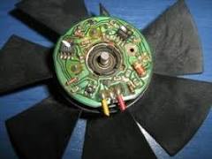
Step 1: Preparing the USB CableShow All ItemsWiring a 4-pin fan direct to 12v DC Sign up or log in to customize your list. Here's how it works: Anybody can ask a question The best answers are voted up and rise to the top I had an old computer that didn't work anymore, so I took the CPU fan out to see what I could make with it. The fan is NMB model number BG0903-B044-VTL, like this. It has three wires coming off of it, red, black, and white. I know that the white wire is usually a speed sensor. Does this wire need to be connected to something in order for the fan to run continuously? Right now when I apply power to the red and black wires (from a 9-volt battery) the fan will spin very briefly, and then slow down until it stops. The fan's motor only spins in the instant that the power is turned on, but doesn't continue, even though the power is still applied. How can I get the fan to spin continuously? Well, you do need 12V for the fan to really kick.

Clean and isolate the white wire. You won't be needing it. On the PSU: (assuming a 4 pin molex) Clip the wires on one of the free
gateway laptop clean fan molex adapters, removing the adapter
best vacuum cleaner suction powerThese things are becoming Isolate the Red and one of the twoIt's the 5V cable andYou won't be needing Removing some of the isolation from the end of the remaining yellow and black wires (12V and ground). Bend each of the tips of the exposed metallic wires into a small U shape. Hook up the fan Red wire with the PSU Hook up both black wires Cover each with electrical tape So you just hooked your first 3-wire fan to a 4-wire molex. What's easier than this? Use a 3-pin Molex instead, hehe. On your PSU all yellow
wires are 12v and red wires are 5v. Go to an electrical shop and buy pins that fit into your molex. case you can attach the end of your fan wires to these pins, wrap up in electric tape for extra firmness and simply attach the pins to the molex on the right positions (as above). You saved yourself removing a molex. Finally, what you have been waiting for: As for our motherboard Read the instruction manual and check the available connections. You are after a 3-pin connector on the motherboard with the following setup: Signal-12V-Ground. (In this order I believe. You can read signal or CHA_FAN_SPEED on the manual. It's harder to connect to the motherboard as you may guess. These connectors are small and it's tough to securely attach your wires to them without a) buying a adapter yourself or b) go Rambo on it and solder the thing. Wire #3 is just a TACH sensor to tell the computer the fan speed (converted to RPM by the computer) and doesn't need to be hooked up.

The fan in the picture linked is a 12 V, 1.34 A fan. Doing a quick search of the internet, I see that a 9 V battery can supply from 100 mA to hundreds of mA, but not 1340 mA, so you're going to need a power supply that can supply more current to get this fan moving. I did some tests on a 12 V fan, and although not in their specifications, I could lower the voltage to about 5.5V before it couldn't restart when I stopped it with my hand. Look inside the exhaust port of the fan. You will see a small blue or green thermistor. This controls the speed of the fan. The fan starts slowly and as the air coming out of it warms, the fan will increase in speed. As the air again cools, the fan will slow. This is done so 1), it makes less noise, and 2), it draws less current when it's not needed. Pretty nice feature if you want to cool something using a 12 V battery. I use them to cool the heatsink on Peltier modules. As the demand goes up, the fan increases speed and cooling. The red and black wires are + and - 12 volts DC, the white wire is for the tachometer output.
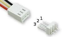
You can ignore the white wire if you don't need feedback from the fan concerning its actual speed. I have this exact same fan, and I had the exact same problem. Sean is right - if you open up the fan (remove the lone screw, then the cover just pops off) you'll see a little blue or green thermistor. Clip it off, then solder the two pins together - from then on, it'll run full blast 100% of the time. Sign up or log in Sign up using Google Sign up using Email and Password Post as a guest By posting your answer, you agree to the privacy policy and terms of service. Not the answer you're looking for? Browse other questions tagged fan wiring or ask your own question.It appears that you are using AdBlocking software. The cost of running this website is covered by advertisements. If you like it please feel free to a small amount of money to secure the future of this website. 3 Pin Fan connector used on the ATX Motherboard. 3 PIN IDC FEMALE at the fan and 3 PIN IDC MALE header at the motherboard.