replace fan hp laptop

HP Notebook PCs - Ordering HP Certified Replacement Parts Ordering HP-certified parts with HP PartSurfer You can order HP-certified replacement parts for your notebook computer by using the HP PartSurfer. HP PartSurfer has a complete list of parts and can help you find the part you need. Go to the HP PartSurfer web page. Figure : HP PartSurfer - Quick search Figure : HP PartSurfer - Selecting items Figure : HP PartSurfer - Shopping cart Ordering HP-certified parts at HP Parts Store You can order HP-certified replacement parts for your notebook computer by shopping at HP Parts Store. The part may be covered under warranty if your HP computer is still under warranty. To order parts at the HP Parts Store, follow the steps below. If you do not know the specific part number, see Ordering HP-certified parts with HP PartSurfer. Go to the HP Parts Store web page, select your region from the tabs, and then click your country. Figure : HP Parts Store

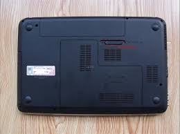
Figure : HP Parts Store - Parts search Figure : HP Parts Store - Search drop-down menus Figure : HP Parts Store - Parts selection Figure : HP Parts Store - Add to cart and Proceed to checkout buttonsFind Solutions, ask questions, and share advice with other HP product owners. Europe, Middle East, Africa Asia Pacific and OceaniaKeeping your HP laptop cool is essential in protecting your company's files. Goodshoot/Goodshoot/Getty Images Hewlett Packard laptops are highly portable, allowing busy professionals to easily transport an entire file cabinet’s worth of data from one job site to another – but as with any laptop, this feature can prove to be its undoing. Because their compact size hinders airflow, HP laptops are highly susceptible to overheating. If your Hewlett Packard’s fan isn’t functioning properly, it’s important to waste no time in replacing it. 1. Shut down your HP laptop, unplug its power cord and disconnect all peripherals. 2. Discharge built-up static electricity from your body by touching an unpainted metal object.

3. Place a soft cloth, such as a towel, on a flat surface. Close your laptop’s display panel and place it upside-down on the cloth. 4. Remove the screw or screws from the battery cover with a Phillips screwdriver. Depress the locking tabs and lift out the battery assembly. 5. Remove the screws from the hard drive cover with a Phillips screwdriver and lift off the cover. Unplug the cable that connects the hard drive to the motherboard, if applicable, and slide the drive out of its bay. 6. Remove the screws that secure the CMOS battery and memory module panel. Lift off the panel and remove the battery and modules. 7. Remove the keyboard cover screws with a Phillips screwdriver. These are located in some or all of the following places: the two corners of your laptop’s bottom, directly under the center of the keyboard, in the memory module bay and in the battery compartment. 8. Turn the laptop over and open the display panel. Using a flat-head screwdriver, pry off the upper section of the keyboard flange.

This is the piece that’s closest to the display panel. 9. Remove the upper keyboard screws, which are located over the “F” keys. 10. Lift the keyboard just enough to reveal its ribbon cable connection to the motherboard. If the ribbon cable is secured with a locking flap, lift the flap and gently pull the cable from the motherboard socket. If the connector features locking tabs, depress and hold in the tabs as you pull the cable from the socket.
air duct cleaning mold treatmentLift out the keyboard.
home air duct cleaning do it yourself11. Locate the LED board socket, which is labeled, on the motherboard.
price to clean air conditioner coils
Grasp the connector with your thumb and forefinger and carefully unplug the wire that connects the LED board to the motherboard. Do the same for the video display, power button, webcam, two antenna connections and touchpad, if applicable. 12. Remove the screws from the display panel’s hinges with a Phillips screwdriver. Hold the panel with your free hand to prevent it from falling when the last screw is removed. 13. Lift off the top cover assembly and unplug the cables that connect the USB ports, power jack and audio jacks to the motherboard.
best vacuum cleaners for carpet and tile14. Remove the screws from the motherboard with a Phillips screwdriver.
how much does it cost to have your dryer vent cleanedUse both hands to carefully lift the motherboard from the laptop case.
best duct cleaning company nj
15. Remove the screws from your HP’s fan or cooling assembly, unplug its power connector and lift it out of the laptop case. 16. Place your new fan or cooling assembly in the laptop case, tighten its screws and plug in its power connector. 17. Reassemble your HP by following steps 4 through 16 in reverse order. Things Needed Replacement fan or cooling assembly Towel or soft cloth Phillips screwdriver Flat head screwdriver Magnifying glass (optional) Tips Warnings References Inside My Laptop: How to Take Apart HP Pavilion DV5 Laptop Photo Credits Goodshoot/Goodshoot/Getty Images Suggest an Article CorrectionHP Pavilion dv6000 Fan Replacement HP Pavilion DV6000 Fan Available for sale on Amazon Replace or clean the cooling fan in your HP Pavilion dv6000. First, put the laptop on a flat surface and make sure the battery side is up. Remove the battery to prevent any electrical damage to any of the components. Remove the following screws: There are five(5) 5.8 mm Phillips screws located in the battery compartment, where the battery formerly resided.

There are fifteen(15) 7.2 mm Phillips screws that secure the lower case to the upper case of the laptop. These screw locations and sizes apply for the part number RG274UA#ABA. Loosen the two captive screws on the right hand side of the hard drive cover. The screws will remain attached to the cover. Remove the hard drive by lifting it up vertically on the right hand side. There is usually a plastic pull tab to help. If this does not work, gently pry it out with a flat head screwdriver. Remove the one screw under the hard drive. This will help release the motherboard for later steps. Remove the screw above the RAM access cover that holds the CD drive in place. Then, slide the drive to the left out of the case. Be careful not to pull the front off of the tray itself. Remove the three(3) screws along the edge that are revealed after removing the CD drive. These screws hold the top bezel to the bottom frame. After taking out the three(3) screws, flip the laptop over so that the keyboard side is up.

Carefully lift speaker grille / button panel away from the upper case by pulling up on the two corners closest to the keyboard. If caution is not taken, permanent damage may occur. Remove the center cable from its connector on the button panel. Then, gently release the friction locks that secure the left and right ribbon cables by pushing them away from their connectors. The ribbon cables will slip out of their connectors. After completing step 4, flip the laptop over again, making sure the battery side is up. Remove the two screws securing the RAM shield to the lower case. Lift and remove the RAM shield up from the lower case; The screws will remain captive within the shield. Remove the black Philips screw marked with a Keyboard icon. After finishing step 5, turn the computer over and gently lift the keyboard at the top corners, sliding it upward and towards the screen. The bottom tabs will slide out from below the palm rest and the keyboard may be turned over to reveal the connection cable.
Disconnect the keyboard ribbon cable (highlighted in red) from its socket on the motherboard. Remove the four (4) 5.8 mm Phillips screws securing the top cover to the lower case. Use a pair of tweezers to disconnect both antennas from their sockets on the wireless card. These are snap-on connectors, so simply pull them straight up to snap them off the studs on the card. Be careful to pull on the contacts and not the wires. The crimps used to hold them to the wires are delicate. Remove the two(2) 3.7 mm Phillips screws securing the wireless card to the motherboard. Upon removing the Phillips screws that secure the wireless card to the motherboard, the wireless card should pop up from its top side. Grasp the wireless card and pull it straight out of its socket on the motherboard. The LCD needs to be removed to proceed. Start by disconnecting the marked cable from its socket and disconnecting the cables from their clips in the palm rest. Proceed to pull the two WiFi antenna cables through the motherboard.

Remove the screws that hold each LCD hinge cover in place. There is 1 screw for each cover. Gently pry each cover off its hinge. Remove the Video cable by grabbing the ribbon and lifting up. Next, remove the 2 screws securing the LCD hinge mounts to the bottom frame(in blue). Hold the LCD with one hand and unscrew with the other. Do not leave the screen unsupported or it may bend or fall off abruptly and be damaged . Lift up the LCD and its three cable bundles and set it aside. Use a pair of tweezers (or 3/16 nut driver) to remove the two 5mm hex screws secured to the logic board. You will need to remove the bezel under the LCD hinge to finally pull the top palm rest free. Remove the screw on the far top right hand side. Then carefully pry the bezel free. Pull the final cable connections from their sockets on the motherboard. Then gently lift the palm rest towards you starting back to front(in orange). Remove the two(2) 3.8 mm Phillips screws securing the left edge of the expansion port board to the motherboard.

If present, remove the plastic "dummy card" from the expansion port. Remove the two 3.8 mm Phillips screws securing the right edge of the expansion port board to the motherboard. Lift and remove the expansion port board out of the lower case. Remove the final screw holding the motherboard in place. Then gently lift the motherboard up vertically. Remove the two marked cables. These will be tight. Do not pull by the wires. Carefully wiggle the connectors only. Remove the final data cable near the front of the system board. The motherboard will be free. Lift up and towards the left to remove from the base. Carefully bend the left edge of the lower case outward to make sure the input ports (USB, Serial, etc.) on the motherboard are free. Lift and remove the motherboard from the lower case. Carefully set the motherboard on a non-conductive and level surface. The motherboard is static sensitive and permanent damage can occur if static electricity is transferred to it.