laptop cooling fan broken
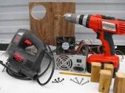
Laptop cooling fan broken? Is your laptop running slow or occasionally freezing up on you? When is the last time you flipped it over to see if the little cooling fan is still turning? Even if it is spinning, is the bottom hot to the touch? All you might need is a laptop cooling pad, but maybe you're like me and you don't like any of the boring plastic models available and would rather make your own and save a handful of dollars in the process. piece of scrap plywood in the barn, cut it to size, lined up the cooling fan hole with the location of the laptop fan, secured the new fan which was scraped out of an old desktop computer power supply Attach the legs, power up your fan and you should notice an increase in the smoothness of operations, and a decrease in the heat coming off theYou might not even need the fan, just the increase in space could make enough difference.I was visiting with our friends Amy and Ryan the other day and noticed a laptop cooler in their garage (a Targus Lap Chill Mat).

I asked whether it was any good (as I’m considering getting one for my laptop) and Ryan said that it was but the cord was broken. He was going to repair it eventually (as he’s certainly qualified) but hadn’t found the time. So I took it home to see if I could repair it.The broken cord, right at the grommet junction. The Amazon reviews show that some people have this problem.The screws for the cooler grill are inside the case…Ryan had started to pry it apart but experience led me to believe this was the wrong way to start.The cover seems to just be a round sleeve.So I tentatively started peeling it up. The adhesive was not strong.I was particularly careful when peeling the narrow bits.The top and bottom pieces that tuck under the grill have a toothed piece attached.The USB cable goes through this notched piece that slips around the grommet.There are two rows of four screws top and bottom.The screws removed and the fan housing exposed. It is held by 5 screws.The USB cord strain relief at bottom.

There was annoying nylon stranding with the copper that I had to separate and cut off.Twisted together and ready for soldering.I insulated the soldered wires with little pieces of electrical tape. I need to buy some tiny shrink tubing.
best steam vacuum cleaner rentalI used shrink tubing over the whole length of the splice.I reassembled (in the reverse order of disassembly) and massaged the cover back into position.HP Pavilion dv6000 Fan Replacement HP Pavilion DV6000 Fan Available for sale on Amazon Replace or clean the cooling fan in your HP Pavilion dv6000. First, put the laptop on a flat surface and make sure the battery side is up. Remove the battery to prevent any electrical damage to any of the components. Remove the following screws: There are five(5) 5.8 mm Phillips screws located in the battery compartment, where the battery formerly resided.

There are fifteen(15) 7.2 mm Phillips screws that secure the lower case to the upper case of the laptop. These screw locations and sizes apply for the part number RG274UA#ABA. Loosen the two captive screws on the right hand side of the hard drive cover. The screws will remain attached to the cover. Remove the hard drive by lifting it up vertically on the right hand side. There is usually a plastic pull tab to help. If this does not work, gently pry it out with a flat head screwdriver. Remove the one screw under the hard drive. This will help release the motherboard for later steps. Remove the screw above the RAM access cover that holds the CD drive in place. Then, slide the drive to the left out of the case. Be careful not to pull the front off of the tray itself. Remove the three(3) screws along the edge that are revealed after removing the CD drive. These screws hold the top bezel to the bottom frame. After taking out the three(3) screws, flip the laptop over so that the keyboard side is up.
Carefully lift speaker grille / button panel away from the upper case by pulling up on the two corners closest to the keyboard. If caution is not taken, permanent damage may occur. Remove the center cable from its connector on the button panel. Then, gently release the friction locks that secure the left and right ribbon cables by pushing them away from their connectors. The ribbon cables will slip out of their connectors. After completing step 4, flip the laptop over again, making sure the battery side is up. Remove the two screws securing the RAM shield to the lower case. Lift and remove the RAM shield up from the lower case; The screws will remain captive within the shield. Remove the black Philips screw marked with a Keyboard icon. After finishing step 5, turn the computer over and gently lift the keyboard at the top corners, sliding it upward and towards the screen. The bottom tabs will slide out from below the palm rest and the keyboard may be turned over to reveal the connection cable.

Disconnect the keyboard ribbon cable (highlighted in red) from its socket on the motherboard. Remove the four (4) 5.8 mm Phillips screws securing the top cover to the lower case. Use a pair of tweezers to disconnect both antennas from their sockets on the wireless card. These are snap-on connectors, so simply pull them straight up to snap them off the studs on the card. Be careful to pull on the contacts and not the wires. The crimps used to hold them to the wires are delicate. Remove the two(2) 3.7 mm Phillips screws securing the wireless card to the motherboard. Upon removing the Phillips screws that secure the wireless card to the motherboard, the wireless card should pop up from its top side. Grasp the wireless card and pull it straight out of its socket on the motherboard. The LCD needs to be removed to proceed. Start by disconnecting the marked cable from its socket and disconnecting the cables from their clips in the palm rest. Proceed to pull the two WiFi antenna cables through the motherboard.

Remove the screws that hold each LCD hinge cover in place. There is 1 screw for each cover. Gently pry each cover off its hinge. Remove the Video cable by grabbing the ribbon and lifting up. Next, remove the 2 screws securing the LCD hinge mounts to the bottom frame(in blue). Hold the LCD with one hand and unscrew with the other. Do not leave the screen unsupported or it may bend or fall off abruptly and be damaged . Lift up the LCD and its three cable bundles and set it aside. Use a pair of tweezers (or 3/16 nut driver) to remove the two 5mm hex screws secured to the logic board. You will need to remove the bezel under the LCD hinge to finally pull the top palm rest free. Remove the screw on the far top right hand side. Then carefully pry the bezel free. Pull the final cable connections from their sockets on the motherboard. Then gently lift the palm rest towards you starting back to front(in orange). Remove the two(2) 3.8 mm Phillips screws securing the left edge of the expansion port board to the motherboard.

If present, remove the plastic "dummy card" from the expansion port. Remove the two 3.8 mm Phillips screws securing the right edge of the expansion port board to the motherboard. Lift and remove the expansion port board out of the lower case. Remove the final screw holding the motherboard in place. Then gently lift the motherboard up vertically. Remove the two marked cables. These will be tight. Do not pull by the wires. Carefully wiggle the connectors only. Remove the final data cable near the front of the system board. The motherboard will be free. Lift up and towards the left to remove from the base. Carefully bend the left edge of the lower case outward to make sure the input ports (USB, Serial, etc.) on the motherboard are free. Lift and remove the motherboard from the lower case. Carefully set the motherboard on a non-conductive and level surface. The motherboard is static sensitive and permanent damage can occur if static electricity is transferred to it.